Boolean Algebra and Truth Tables
Learning Objectives
By the end of this lesson, you should be able to:
- represent digital signals as Boolean variables;
- write truth tables for basic and compound logic expressions;
- convert between truth tables, sum-of-products, and product-of-sums forms;
- apply the main Boolean laws, especially De Morgan's theorems;
- simplify small logic expressions and check the result by truth table;
- avoid common mistakes that cause wrong gates or active-low logic errors.
Why Boolean Algebra Matters
Digital electronics is built from circuits that treat voltage ranges as two logic states:
| Logic idea | Common name | Typical voltage meaning |
|---|---|---|
0 |
false, low, off | near ground |
1 |
true, high, on | near the logic supply |
The exact voltage thresholds depend on the logic family. A 5 V CMOS input and a 1.8 V FPGA input do not use the same limits, but the logic abstraction is still Boolean: each valid input is interpreted as either 0 or 1.
Boolean algebra gives you a compact way to design and check digital circuits before choosing gates, ICs, FPGA logic, or firmware bit operations.
Boolean Variables and Operators
A Boolean variable such as A, B, or ENABLE can only be 0 or 1.
The basic operators are:
| Operation | Common symbols | Meaning |
|---|---|---|
| NOT | A', ~A, !A, overline(A) |
invert the value |
| AND | A B, A . B, A & B |
true only when all inputs are true |
| OR | A + B, `A |
B` |
| XOR | A xor B, A ^ B |
true when inputs are different |
In electronics schematics you will also see NAND, NOR, and XNOR gates. These are inverted versions of AND, OR, and XOR.
Basic Truth Tables
A truth table lists every possible input combination and the corresponding output. For n inputs there are:
number of rows = 2^n
For two inputs, 2^2 = 4 rows.
| A | B | NOT A | A AND B | A OR B | A XOR B |
|---|---|---|---|---|---|
| 0 | 0 | 1 | 0 | 0 | 0 |
| 0 | 1 | 1 | 0 | 1 | 1 |
| 1 | 0 | 0 | 0 | 1 | 1 |
| 1 | 1 | 0 | 1 | 1 | 0 |
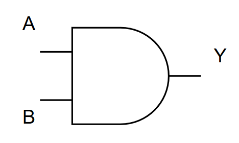
The table is often more reliable than a verbal description. If two circuits have identical truth tables, they implement the same Boolean function.
Universal Gates
NAND and NOR are called universal gates because either one can implement any Boolean function.
| Gate | Expression | Output is 0 when |
|---|---|---|
| NAND | (A B)' |
all inputs are 1 |
| NOR | (A + B)' |
at least one input is 1 |
Examples using NAND only:
NOT A       = A NAND A
A AND B     = (A NAND B) NAND (A NAND B)
A OR B      = (A NAND A) NAND (B NAND B)
This is not just a textbook trick. Many real IC and FPGA synthesis tools map logic into small universal structures because they are efficient to manufacture.
Boolean Laws You Actually Use
| Law | AND form | OR form |
|---|---|---|
| Identity | A . 1 = A |
A + 0 = A |
| Dominance | A . 0 = 0 |
A + 1 = 1 |
| Idempotent | A . A = A |
A + A = A |
| Complement | A . A' = 0 |
A + A' = 1 |
| Commutative | A B = B A |
A + B = B + A |
| Associative | (A B) C = A (B C) |
(A + B) + C = A + (B + C) |
| Distributive | A(B + C) = AB + AC |
A + BC = (A + B)(A + C) |
| Absorption | A(A + B) = A |
A + AB = A |
De Morgan's Theorems
De Morgan's theorems are essential when converting between active-high and active-low logic:
(A . B)' = A' + B'
(A + B)' = A' . B'
For three inputs:
(A . B . C)' = A' + B' + C'
(A + B + C)' = A' . B' . C'
A practical memory rule is: break the inversion bar, change AND to OR or OR to AND, and invert each variable.
Worked Example 1: Simplify an Expression
Simplify:
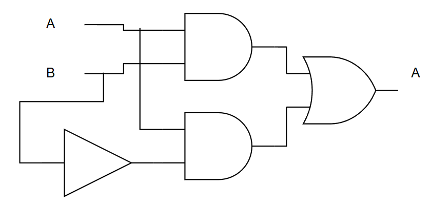
Y = A B + A B'
Step by step:
Y = A B + A B'
Y = A (B + B')       factor A
Y = A (1)            B + B' = 1
Y = A
So the two-gate expression is equivalent to a wire carrying A.
Truth-table check:
| A | B | B' | AB | AB' | Y | A |
|---|---|---|---|---|---|---|
| 0 | 0 | 1 | 0 | 0 | 0 | 0 |
| 0 | 1 | 0 | 0 | 0 | 0 | 0 |
| 1 | 0 | 1 | 0 | 1 | 1 | 1 |
| 1 | 1 | 0 | 1 | 0 | 1 | 1 |
The Y column matches the A column for every row.
Worked Example 2: Build a Truth Table
Create the truth table for:
Y = A B' + A' C
There are three variables, so there are 2^3 = 8 rows.
| A | B | C | B' | A B' | A' | A' C | Y |
|---|---|---|---|---|---|---|---|
| 0 | 0 | 0 | 1 | 0 | 1 | 0 | 0 |
| 0 | 0 | 1 | 1 | 0 | 1 | 1 | 1 |
| 0 | 1 | 0 | 0 | 0 | 1 | 0 | 0 |
| 0 | 1 | 1 | 0 | 0 | 1 | 1 | 1 |
| 1 | 0 | 0 | 1 | 1 | 0 | 0 | 1 |
| 1 | 0 | 1 | 1 | 1 | 0 | 0 | 1 |
| 1 | 1 | 0 | 0 | 0 | 0 | 0 | 0 |
| 1 | 1 | 1 | 0 | 0 | 0 | 0 | 0 |
From Truth Table to Expression
There are two standard forms.
Sum of Products
Sum of products, or SOP, ORs together the rows where the output is 1.
For XOR:
| A | B | Y |
|---|---|---|
| 0 | 0 | 0 |
| 0 | 1 | 1 |
| 1 | 0 | 1 |
| 1 | 1 | 0 |
Rows with Y = 1 are:
A=0, B=1 -> A'B
A=1, B=0 -> AB'
So:
Y = A'B + AB'
Product of Sums
Product of sums, or POS, ANDs together the rows where the output is 0.
For the same XOR table:
Y = (A + B)(A' + B')
SOP is often easier when there are few 1 rows. POS is often easier when there are few 0 rows.
Practical Design Example: Armed Alarm
Requirement:
S = 1when the system is armed;D = 1when the door is open;W = 1when the window is open;- alarm output
Ashould be1only when armed and either opening is detected.
Expression:
A = S(D + W)
Truth table:
| S | D | W | A |
|---|---|---|---|
| 0 | 0 | 0 | 0 |
| 0 | 0 | 1 | 0 |
| 0 | 1 | 0 | 0 |
| 0 | 1 | 1 | 0 |
| 1 | 0 | 0 | 0 |
| 1 | 0 | 1 | 1 |
| 1 | 1 | 0 | 1 |
| 1 | 1 | 1 | 1 |
The expanded form is:
A = S D + S W
Both forms are correct. The factored form is easier to read; the expanded form maps directly into AND-OR gates.
Boolean Algebra in HDL and Firmware
In hardware description languages, Boolean algebra becomes synthesizable logic:
assign alarm = armed & (door_open | window_open);
assign xor_y = (~a & b) | (a & ~b);
In C, distinguish logical operators from bitwise operators:
bool alarm = armed && (door_open || window_open);  // logical true/false
uint8_t masked = value & 0x0F;                     // bitwise masking
Use logical operators for conditions and bitwise operators for individual bits inside registers.
Common Mistakes
| Mistake | Why it fails | Fix |
|---|---|---|
Treating A + B like arithmetic addition |
Boolean 1 + 1 is still 1 |
Read + as OR |
| Applying De Morgan's halfway | (AB)' is not A'B' |
Change the operator too |
| Forgetting active-low signals | RESET_N = 0 may mean reset is active |
Name active-low signals with _N or a bar |
| Mixing logical and bitwise C operators | && and & do different jobs |
Use && for truth, & for bits |
| Ignoring invalid voltage levels | Real inputs are not always clean 0 or 1 |
Check logic thresholds and noise margin |
Summary
Boolean algebra is the working language of digital circuits. Truth tables give the complete behavior, Boolean laws reduce unnecessary gates, and De Morgan's theorems help you reason about inverted and active-low logic. When in doubt, build the truth table and compare every row.
Further Reading
- M. Morris Mano and Michael Ciletti, Digital Design
- Stephen Brown and Zvonko Vranesic, Fundamentals of Digital Logic with Verilog Design
- Texas Instruments, Logic Guide
- Nexperia and TI datasheets for 74HC logic families